Helicopter Dynamics
Helicopter Rotor Coning & G-Load Centrifugal Balance
FAA Ref: FAA-S-ACS-15 Area I Task F (Performance and Limitations)
Scenario & Physics Summary
Upward bending of rotor blades caused by the balance between aerodynamic lift pulling UP and centrifugal force pulling OUT.
Interactive 3D Visual Plates & Scenario Media

Plate 1: Helicopter Rotor Coning & G-Load Centrifugal Balance

Plate 2: Helicopter Rotor Coning & G-Load Centrifugal Balance
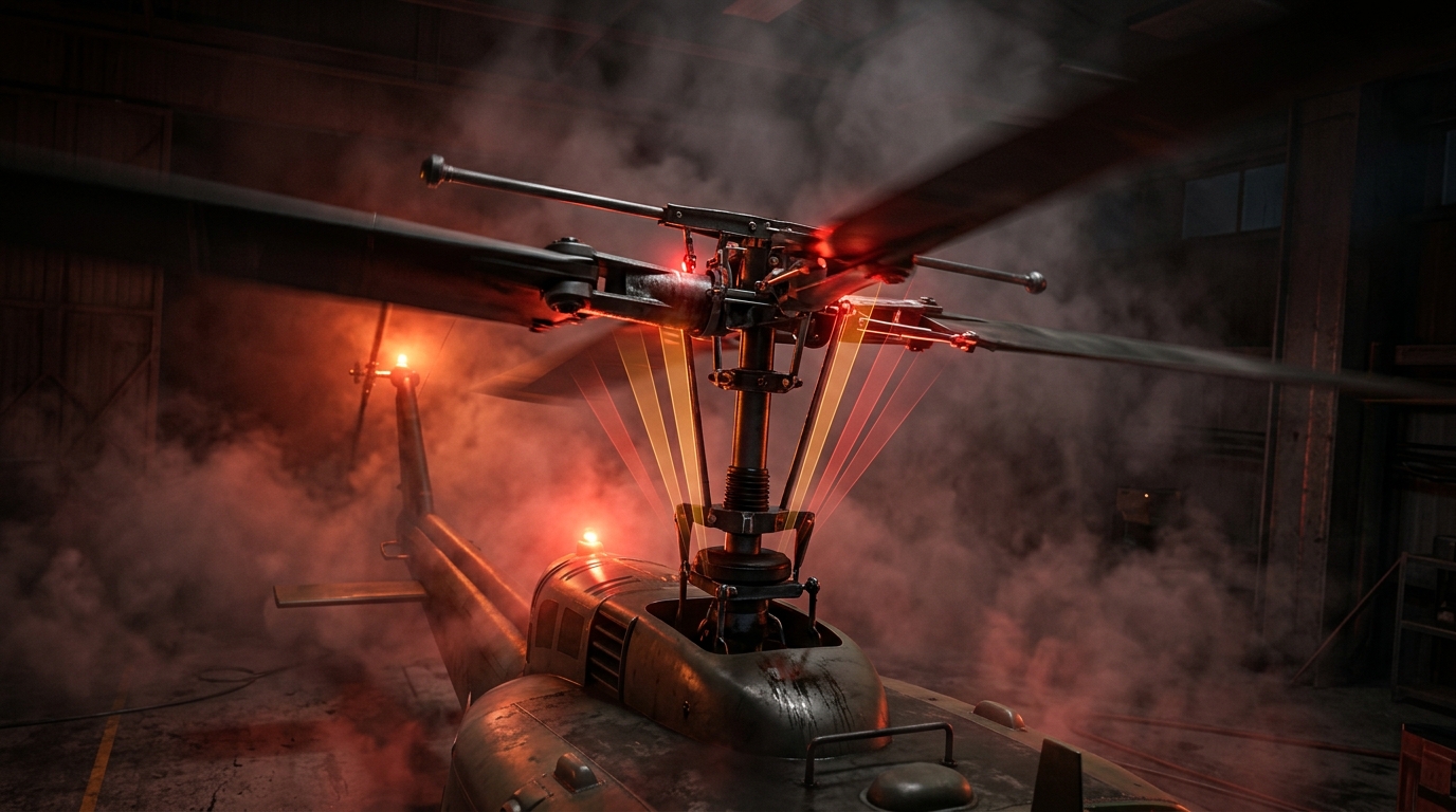
Plate 3: Helicopter Rotor Coning & G-Load Centrifugal Balance

Plate 4: Helicopter Rotor Coning & G-Load Centrifugal Balance
Aerodynamic & Operational Physics
- Lift acts upward on rotor blades; Centrifugal force (F_c = mω²r) acts outward horizontally.
- The resultant vector creates a upward cone shape (Coning Angle).
- High gross weight, low rotor RPM, or high G-load turns increase coning angle.
- Excessive coning reduces effective disc area, decreases total lift, and risks structural blade bending.
FAA Exam Gotcha Alert
Exam Trap: Low rotor RPM increases coning angle because centrifugal force drops dramatically (proportional to RPM squared).
Frequently Asked Questions & Exam Explanations
What two forces determine rotor blade coning angle?
Aerodynamic lift (pulling up) and centrifugal force (pulling outward).
 Aero Academic